
Unlike conventional loading of complex oversized loads, 3D load planning for heavy machinery provides a more reliable solution. Transforms detailed cargo data from dimensions, weight, center of gravity, support points & lashing requirements into a visual simulation that logistics teams can use to review and refine prior to any physical movement, saving time and saving money. This is particularly important for large, heavy, low symmetry items with high value and challenging to reposition once on a container or trailer, such as heavy machinery.
For more simple loads with simple manual measurements, 2D drawings, experience, and adjustments on-site, traditional loading may be applicable. For OOG goods such as construction equipment, generators, transformers or industrial presses, a slight error in measurement or assumption can create fit problems, bad weight distribution, inaccessible lashing points, or cause the carrier to delay approval of the shipment. 3D load planning is more than simply a visual design tool – it’s a risk-control measure that enables logistics teams to spot fit, balance, securing, and handling issues before they turn into costly onsite problems. Many shippers think that loading problems can always be solved on site, but it is not always safe, convenient or inexpensive when there is heavy machinery involved.
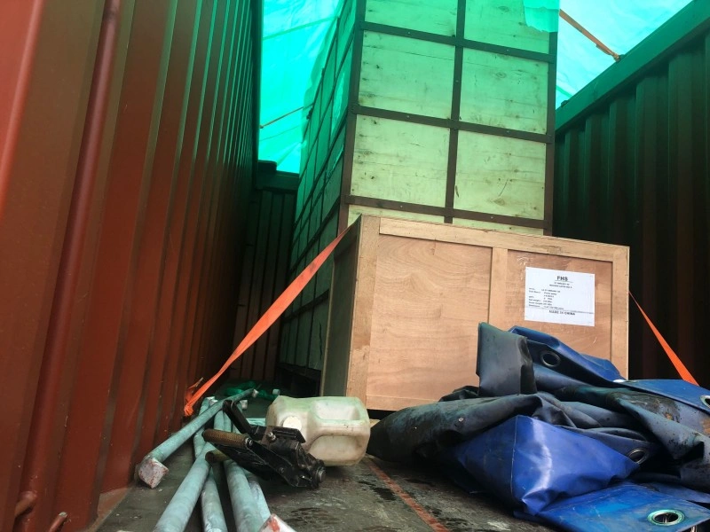
What Is 3D Load Planning?
The 3D load planning is based on precise digital models of the cargo and the transport equipment and simulates the loading process in a virtual model. It enables the planners to test the fit, balance and securing of heavy machinery on a flat rack, open top, low bed or modular trailers or even on a breakbulk vessel.
This approach considers important parameters such as overhang, clearance, center of gravity, supports placement and lashing access before they happen. It is based on accurate measurements, drawings, photographs and occasionally CAD (computer-aided design) models, not assumptions. It can give a good idea of any potential problems that may not be seen from a 2D plan when the equipment is oversized and irregular.
| 3D Load Planning Element | What It Helps Confirm |
| Cargo Dimensions | Whether the machinery fits the selected trailer, container, or deck space |
| Final Packed Size | Whether packaging changes the transport envelope |
| Load Position | Where the cargo should sit for balance and securing |
| Center of Gravity | How cargo stability may affect loading and transport |
| Support Points | Where timber, steel supports, or saddles should be placed |
| Lashing Access | Whether chains, straps, or securing points remain reachable |
| Clearance | Whether cargo height, width, or protrusions create restrictions |
| Overhang | Whether the cargo exceeds platform or container limits |
What Is Traditional Loading?
Traditional loading is mostly based on manual planning and experience of the operators and adjustments in real-time during the loading process. Teams assess the cargo characteristics by measuring on site, referring to a 2D drawing or photograph and making a judgement based on previous similar cargoes and the judgment of the crane operators, riggers and supervisors.
This has been the industry norm for decades, and is still working well for many simple applications. It consists of attempting to position physically and solve problems on the spot when problems occur.
| Traditional Loading Method | Practical Meaning |
| Manual Measurement | Cargo size is measured and applied to the loading plan manually |
| 2D Drawing Review | Engineers or operators review flat drawings instead of 3D layouts |
| Experience-Based Positioning | Loading decisions rely heavily on prior similar shipments |
| On-Site Adjustment | Cargo position may be corrected during loading |
| Visual Inspection | Photos and site checks guide the loading team |
| Trial Loading | Cargo fit or balance may be confirmed only during physical operation |
| Operator Judgment | Crane, trailer, and lashing teams make practical decisions on site |
3D Load Planning vs Traditional Loading: Key Differences
The most significant difference between 3D load planning and traditional loading is that it can identify and solve potential problems before the heavy machinery ever arrives at the loading area. Unlike traditional approaches, which rely on experience and in-site solutions, 3D planning offers a common visual reference, enhancing the accuracy and communication.
For oversized machinery with tight clearance, irregular geometry, or complex securing requirements, advanced OOG load planning helps identify fit, balance, support, and lashing issues before the cargo reaches the loading site.
| Factor | 3D Load Planning | Traditional Loading |
| Cargo Fit Review | Visual simulation before loading | Often confirmed through drawings or on-site checks |
| Error Detection | Can reveal clearance, overhang, and layout issues early | Problems may appear during loading |
| Load Positioning | Planned digitally based on layout and support points | Adjusted by experience and site conditions |
| Center of Gravity Review | Easier to visualize and discuss | May rely on manual calculation and judgment |
| Lashing Access | Can be checked before loading | Sometimes discovered after cargo is positioned |
| Communication | Easier for shipper, carrier, port, and loading team to understand | May depend on verbal explanation and 2D drawings |
| Rework Risk | Lower when data is accurate | Higher if measurements or assumptions are wrong |
| Best Use Case | Complex OOG cargo, multiple units, tight fit, high-value machinery | Simple cargo with familiar dimensions and enough clearance |
Why 3D Load Planning Matters for Heavy Machinery
Heavy machinery comes in a number of sizes, weights, shapes and has sensitive components which make it a special challenge to transport. After it is mounted, the unit can be very expensive and difficult to move because of the crane needed to move the unit, site restrictions, and the potential of damaging the unit.
3D load planning is important as it enables teams to solve these problems virtually before they ever even occur in real life.
| Heavy Machinery Challenge | How 3D Load Planning Helps |
| Irregular Shape | Shows how protrusions, attachments, or frames affect fit |
| Heavy Weight | Helps plan load position and support points |
| High Center of Gravity | Supports stability review before movement |
| Limited Lashing Points | Checks whether securing access remains available |
| Fragile Components | Helps avoid contact pressure on sensitive areas |
| Tight Container Fit | Reduces risk of open top or flat rack mismatch |
| Crane Time Cost | Reduces trial-and-error loading at site |
| Carrier Approval | Provides clearer visual support for load plan review |
| Multi-Unit Cargo | Helps arrange several components efficiently and safely |
Key Benefits of 3D Load Planning for Heavy Machinery
Beyond the aesthetic appeal of the visuals, the application of 3D load planning can deliver significant operational advantages in terms of safety, efficiency and cost management for the transport of large machinery.
| Benefit | Practical Value |
| Fit Confirmation | Reduces the chance of trailer, container, or deck mismatch |
| Better Equipment Selection | Helps choose flat rack, open top, lowbed, modular trailer, or breakbulk option |
| Load Position Accuracy | Supports balance, support, and securing planning |
| Lashing Access Review | Prevents cargo from blocking chains, straps, or anchor points |
| Reduced Rework | Avoids costly repositioning after loading begins |
| Clearer Communication | Helps shippers, carriers, ports, and loading teams review the same plan |
| Improved Approval Support | Provides visual reference for carrier or terminal review |
| Lower Damage Risk | Helps avoid contact points, poor support, or unstable loading |
| Better Schedule Control | Reduces delays caused by last-minute loading problems |
How 3D Load Planning Supports Flat Rack and Open Top Shipments
Everything from securing, to safe transport, depends on effective securing, which is possible with the aid of 3D load planning, enabling you to plan your lashing, blocking and bracing with complete visibility of the final configuration.
| Shipment Type | 3D Load Planning Focus |
| Flat Rack Container | Over-width, over-height, overhang, lashing points, and base support |
| Open Top Container | Wall clearance, top loading access, cargo height, and cover feasibility |
| Lowbed Trailer | Total loaded height, support points, axle load, and stability |
| Modular Trailer | Axle configuration, cargo footprint, support points, and turning clearance |
| Breakbulk Shipment | Lifting points, stowage position, support design, and securing method |
| Multi-Unit Shipment | Space utilization, separation, contact risk, and loading sequence |
How 3D Load Planning Improves Lashing, Blocking, and Bracing Design
Traditional loading is not a thing of the past—it is a feasible option for numerous less complex heavy machinery shipments because the risks are not elevated, and experience can be relied on to effectively manage loading.
| Securing Design Area | How 3D Planning Helps |
| Lashing Angle | Shows whether chains or straps can be applied at suitable angles |
| Anchor Point Access | Confirms that cargo does not block securing points |
| Blocking Position | Helps place blocks against structurally strong areas |
| Bracing Layout | Shows where bracing can stabilize irregular shapes |
| Support Placement | Aligns timber or steel supports with cargo load paths |
| Contact Protection | Identifies areas needing padding or edge protection |
| Cargo Movement Direction | Helps plan restraint against forward, backward, and side forces |
| Inspection Access | Ensures securing can be checked after loading |
When Traditional Loading May Still Be Suitable
In more complex and/or higher risk situations, 3D load planning will give you detailed forward-thinking capabilities to safeguard cargo and schedule.
| Traditional Loading May Work When | Why Risk Is Lower |
| Cargo Shape Is Simple | Fit and securing are easier to judge |
| Dimensions Are Within Normal Limits | Clearance and transport equipment mismatch risk is lower |
| Similar Cargo Has Been Loaded Before | Operators can rely on proven experience |
| Site Space Is Sufficient | Repositioning is easier if needed |
| Lashing Points Are Easy to Access | Securing method is straightforward |
| Center of Gravity Is Low and Stable | Stability risk is more manageable |
| Cargo Is Not Highly Sensitive | Minor repositioning is less likely to cause damage |
When 3D Load Planning Is Strongly Recommended
The first step to successful 3D load planning is detailed and accurate information from the cargo plan and transport plan, verified.
| Situation | Why 3D Load Planning Is Recommended |
| Tight Fit | Confirms clearance before cargo reaches the loading site |
| Irregular Cargo Shape | Helps identify protrusions, contact points, and overhang |
| High-Value Equipment | Reduces trial-and-error handling risk |
| Multiple Cargo Units | Improves layout, sequence, and space utilization |
| Heavy Point Loads | Supports support placement and deck load review |
| High Center of Gravity | Helps evaluate stability and securing design |
| Limited Lashing Access | Checks whether securing remains possible after loading |
| Carrier Approval Needed | Provides clearer load plan evidence for review |
| Multi-Modal Transport | Helps coordinate road, port, and ocean loading stages |
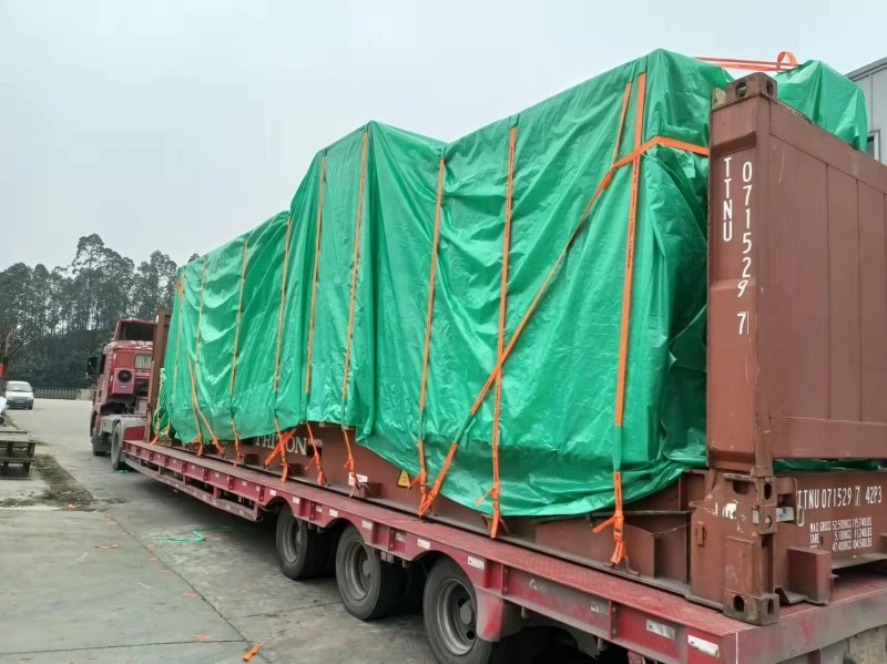
What Information Is Needed for 3D Load Planning?
There are traps that even an experienced team can fall into that can jeopardize their loading effort. These are some common problems we’ve experienced with OOG projects.
| Information Needed | Why It Helps |
| Verified Cargo Dimensions | Builds accurate cargo model and fit review |
| Final Packed Size | Prevents packaging-related mismatch |
| Gross Weight | Supports load position and equipment selection |
| Center of Gravity | Helps evaluate stability and load balance |
| Lifting Points | Supports loading sequence and crane planning |
| Support Points | Helps place timber, steel supports, or saddles correctly |
| Drawings / 3D Model | Improves model accuracy and planning detail |
| Cargo Photos | Shows protrusions, attachments, and fragile areas |
| Transport Equipment Data | Confirms trailer, flat rack, open top, or deck dimensions |
| Lashing Point Locations | Helps design securing layout |
| Loading Site Conditions | Helps evaluate crane access and positioning limits |
Common Mistakes in 3D Load Planning and Traditional Loading
Even experienced teams can fall into traps that undermine loading success. Here are some frequent issues we’ve observed in OOG projects.
| Mistake | Possible Consequence |
| Unverified Dimensions | Digital plan may not match actual cargo |
| Ignoring Packed Size | Cargo may exceed planned trailer or container limits |
| No Center-of-Gravity Review | Stability and lifting risks may remain hidden |
| No Field Confirmation | Site restrictions may make the plan impractical |
| Outdated Drawings | Cargo modifications may cause fit or securing problems |
| Ignoring Lashing Access | Cargo may be loaded but impossible to secure properly |
| No Equipment Data | Trailer or container mismatch may occur |
| Overreliance on Experience | Complex cargo risks may be missed |
| No Plan Sharing | Loading team may not follow the intended layout |
| No Final Inspection | Deviations from plan may go undocumented |
Common Misunderstandings About 3D Load Planning
There are a number of misunderstandings that may hinder shippers from leveraging 3D load planning for heavy machinery:
- 3D load planning is not just for extremely large cargo; it is useful anytime the fit, balance, and securing of cargo is in question.
- The more accurate the measurement information, the more accurate the 3D model will be.
- 3D planning is not a substitute for supervision on the ground or the skills of experienced operators.
- While in some cases, traditional loading is suitable, in others, the additional layer of review provided by traditional loading can work well for the complex OOG heavy machinery.
- The visual plan is not a single solution, but a tool to facilitate communication between teams, carriers and ports.
- Despite the planning done in 3D, it’s important to always take final loaded photos and do physical inspections.
- It is not intended to supplant good lashing, route planning, or carrier approval procedures.
Conclusion — 3D Load Planning Helps Reduce OOG Loading Uncertainty
When sending oversized, irregular, high-value or difficult-to-load heavy machinery, the benefits of 3D load planning are apparent, as opposed to conventional loading. Teams can predict and prevent issues with cargo placement, support points, clearance, center of gravity, and access for securing, before they even start, which results in smoother operations and less surprises.This digital solution, in tandem with the field expertise, can be a tremendous advantage for more complex OOG projects, but may be less appropriate for simpler loads. Accurate cargo data, a complete 3D simulation, sound engineering judgment, experienced loading crews and careful on-site supervision will deliver the best results. The approach is balanced, enabling industrial exporters and project teams to deal with the inevitable uncertainty while transporting heavy machinery more effectively.